WEAK HNO₃ NITRIC ACID DUAL PROCESS
Overview
ESPINDESA leaded the European high pressure process in the 70’s and since then has continuously updated this technology to deal with the most severe environmental regulations and high cost of energy.
NITRIC ACID is manufactured from Ammonia in the form of a solution of HNO₃ in water. Concentrations of 55-60% HNO₃ are used in the Fertilizer Industry while azeotropic concentrations (65%-70% HNO₃) are required by general procedures in the Chemical Industry, mainly organic nitrations.
ESPINDESA leaded the European high pressure process in the 70’s and since then has continuously updated this technology to deal with the most severe environmental regulations and high cost of energy. Plants for the Fertilizer Industry are still being designed by ESPINDESA with this technology.

In the last years the Industry demands giant plants and, in some cases, azeotropic concentration. Early in the 2000’s ESPINDESA improved their dual pressure process featuring:

In the last years the Industry demands giant plants and, in some cases, azeotropic concentration.
Process Description
Ammonia oxidation
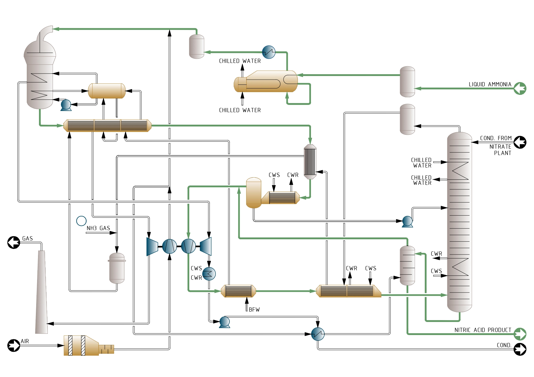
The process air is filtered and compressed up to 3-4 bar in the first stage of the compressor set.
The evaporated ammonia is reheated, filtered and mixed with process air before entering the ammonia burner where Pt-Rh catalyst and getter gauzes are placed. The temperature reaches 870° C. The reactor can include a N,0 abatement catalyst to reduce N,0 to levels lower than 50 ppm in the tail gas.
The heat of the process gas is recovered in a series of heat exchangers, where the temperature decreases from 870°C to 145°C. At this point the gases enter the low-pressure cooler-condenser, which cools them below the dew point, so most of the water produced in the ammonia oxidation reaction condenses in the form of a 30% nitric acid stream.
This is separated from the gas and pumped to the appropriate tray of the absorber.
Process gas compression and cooling
The dry cool process gases are mixed with the secondary air after it has been used in the bleaching tower to strip out most of the free NOX remaining in the product acid. Then are compressed to 8-11 bar what rises the temperature up to 200° C.
In the ducts downstream the compressor, the NO contained in the process gas reacts with the oxygen of the secondary air and is oxidized to NO,. Two further heat exchangers lower the temperature of the process gases to 50° C and enters the absorption tower.
Absorption
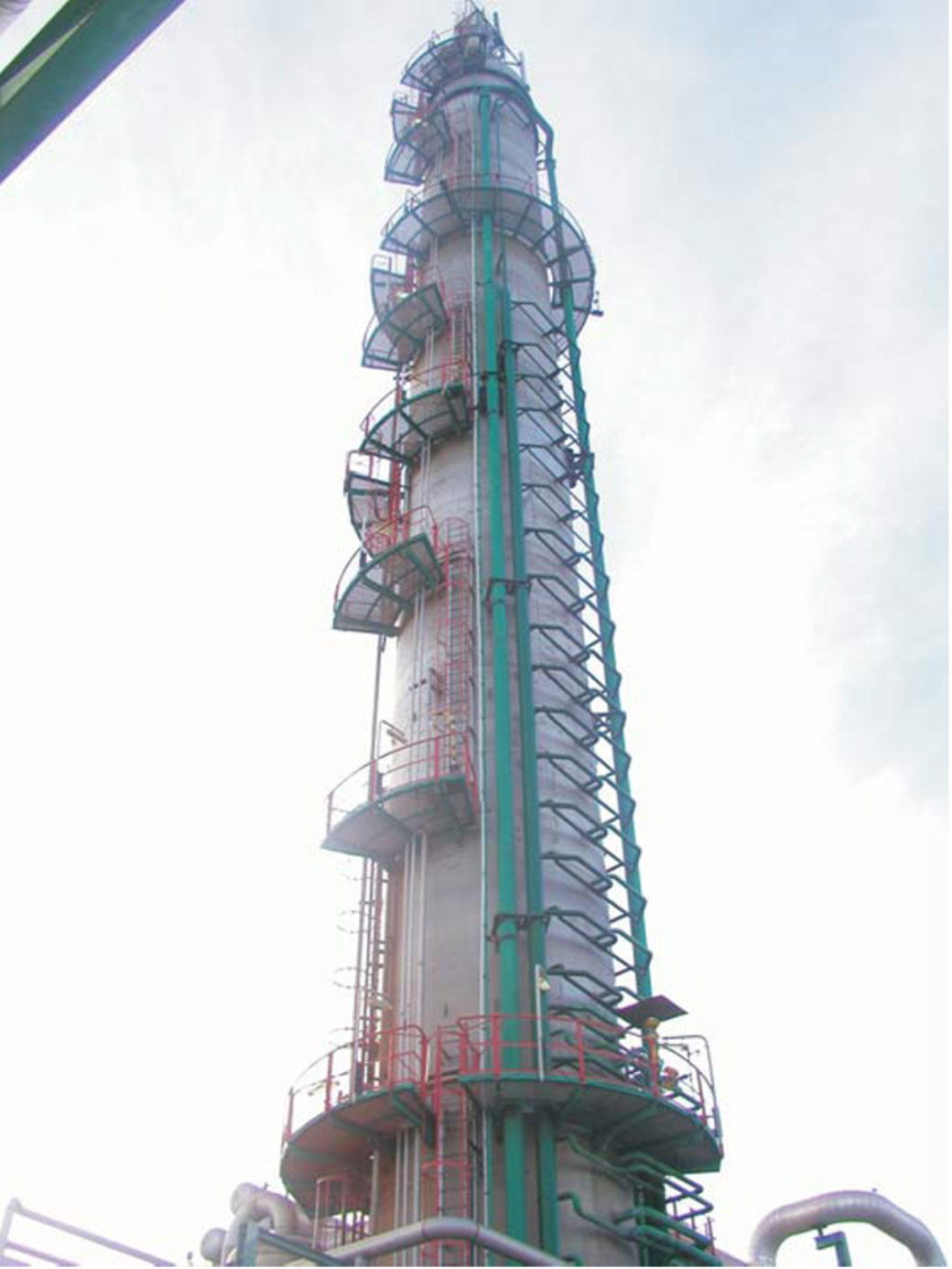
By the time the gases reach the inlet of the absorption tower the oxidation of NO to NO, has already been completed. The internals of the absorber are a set of sieve trays with integral cooling coils. The number of trays depends on the tail gas NOx content permitted in the exhaust gas. Where that could be designed below 200 ppm, a catalyst for DeNOx abatement may be advisable.
The acid leaving the bottom of the absorption column is a reddish colour due to the presence of dissolved free NO. This is removed by countercurrent contact with the secondary air in a small sieve tray column. After bleaching, the acid is colourless and contains less than 20 ppm NO2•
The tail gas leaves the absorption tower at 10 bar and 25° C and is reheated to 420°C in three heat exchangers. The gases are sent to the gas turbine, which recovers 70% of the power needed to drive the compressor set. The rest of the power is provided by the steam turbine.
Operating consumptions
The following table summarizes the main specific materials and utilities consumption per ton of HNO, for a 1,000-t/d plant.
- Ammonia 281.5 kg
- Steam (export) 650 kg
- Catalyst, net (as Pt) 30 mg
- Electric power 9 kWh
Process Flow Diagram


